A layman’s description of how antennas work, plus some related experiments. Physics is strange when you think about it.
I’ve been working with electronics since I was about five. (Not an exaggeration. I “fixed†one of my two-battery-requiring cars with one good battery and some wire.) I sailed through high school electronics, and went on to get professional training in the field. But I’m still pretty mystified by radio waves.
So here’s my set of experiments and a written journal of my learning process. I’m going to figure out Radio, RF, antennas, wave propagation, and be able to explain it to a beginner. My goal is to create a device that harvests ambient RF from the air and illuminates (possibly intermittently) an LED.
First off, DC circuits. Most people have seen something like this, or can figure it out just by looking. (Schematic diagrams courtesy of the iCircuit simulator on OS X)
Due to a chemical reaction, the nine volt battery produces a constant potential of 9 volts. The longer side in the diagram is the + terminal. The squiggly line is a resistor, a device that slows the flow of electricity. The arrow is a LED, a light emitting diode. In this configuration, it would light up, though not terribly brightly. In a circuit like this, the wires can be treated as if they have no resistance at all, because compared to anything else in the circuit, they effectively are zero resistance. So measuring the voltage, say at the top of the battery terminal, is within a rounding error of the measurement on the left-hand side of the resistor.
This circuit is static and simple. In particular, there’s no energy storage anywhere. Current is always proportional to voltage divided by resistance (Ohm’s Law). Compare with this circuit:
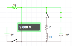
Same 9 volt supply and a limiting 1k resistor. But also two more branches on the right. The rightmost one is a capacitor. As the diagram indicates, it is essentially two metal plates separated by an insulator. This has the ability to store energy in the form an electric field. Notice that the voltmeter still reads the full 9 volts, even though the switch in the lower-left is open. The battery has been disconnected from the circuit, but it’s still live. (This, by the way, is why old CRT-style TV sets can be dangerous to poke around inside, even after they’re unplugged.)
As further evidence that energy is being stored, when the circuit is first turned on, the voltmeter doesn’t instantly snap up to 9 volts. It gradually builds up, because the capacitor is charging.
The other branch in the circuit is an inductor, or a a coil. This can store energy in the form of a magnetic field. (The 10 ohm resistor is to model the inevitable resistance in the windings of the coil. Without it, this simulator assumes a perfect conductor which throw things off a bit.)
What would happen if we closed the switch on the inductor circuit? Well, the energy from the capacitor would suddenly gush through the inductor, which stretch out a magnetic field around the coil, like a rubber band. Then the magnetic field would collapse, sending a new burst of energy into the capacitor, and so forth. Current will slosh back and forth in the circuit until the losses through the resistor diminish the impulse. The circuit would ring like a tuning fork, though with the values here, the frequency is only around 5 cycles per second.
Within the coils of the inductor, we can no longer assume that all voltages and currents will be equal, because it is interacting with the outside world through a magnetic field. Because there is more going on than simple DC, the simplifying assumption from the first circuit no longer holds. Voltage and current may not be directly proportional, because we have to account for stored energy.
So what in the world is a radio wave then? How is visible light, or an X-Ray, the same as an AM radio broadcast? We need more theory to get there.
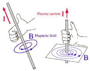
Every wire that conducts electricity produces a magnetic field (and every moving magnetic field produces current in a conductor) like this:
(image: Wikimedia Commons)
If you put iron filings on paper, ran a wire through perpendicularly as shown here, and put a strong current through the wire, you’d get a nested donut pattern. (Incidentally, this is why inductors are coils. That shape makes all the magnetic donuts on every turn of the wire point the same way and sum together.) My electric toothbrush uses magnetic induction to charge. But this still isn’t a radio wave.
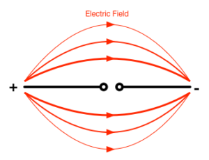
A closely related concept is an electric field. While the magnetic field is caused by current (flow), an electric field is caused by voltage (potential). Every charged particle exhibits a field like this:
(image: Wikimedia Commons)
When you combine an electric field with a magnetic field, amazing things can happen. Like in the circuit above where energy sloshed back and forth, electric and magnetic fields can support each other and propagate, that is, travel through space at the speed of light.
Probably the most straightforward math comes from a “dipole†antenna, which we can make by taking twin-lead wire and separating out the ends. This is most efficient when each end of the T is half a wavelength of the signal. (For example, the speed of light ~= 300M m/sec. So your 2.4Ghz wifi signal has a wavelength of ~ 300M / 2400M = 0.125 m, or a hair under 5 inches.)
If you drive this antenna at its resonant frequency, you could measure the current along various points of either side of the dipole, and you’d measure different values. This isn’t a simple DC circuit! It took me a while to figure out how to visualize this, but you need to start with the current. At the extreme end of the wires, the current will always be zero. Think of a long, arterial one-way street. At the very end, there will always be no traffic, but the farther you get toward the main road, the more traffic there will be coming and going. You can visualize it like this. The black represents the physical wires of the antenna, and blue is a graph of the current at a given point along the wire.
Remember that current flow means there’s a magnetic donut circling the wire, proportional in strength to the amount of current flow.
This flow means that electric charge will accumulate, being strongest at the very ends of the wires. Which in turn means there will be an electric field that looks very much like our diagram above.
The applied signal, being a sine wave, drops to zero a quarter of a cycle later, and these electric fields, supported by the donut magnetic fields, slosh back and detach from the wire to become closed loops in space, and then proceed to propagate. The cycle repeats, switching polarity each time.
The wikipedia page for dipole antenna has some animated gifs which may or  may not help you visualize this.
I welcome your feedback. Coming up next: some experiments. If you have suggestions, I’d love to hear them. -m


