Here’s the manual I wish had been included with the 8x8x8 LED cube kit I picked up on Amazon. Technically there’s already a manual available if you know where to look, but it’s poorly translated and difficult to follow in places. There’s several very similar kits out there, but the LED assembly process is the same, as far as I can tell.
Tools:
- Temperature controlled soldering station (needs to be hot to work quickly–but not too hot)
- Fine solder (you’ll thank me later)
- No-clean soldering Flux (plus toothpicks to spread it on thin)
- Narrow needle-nose pliers
- Soldering tweezers
I will skip over the details of soldering the board itself. There’s nothing new or particularly difficult about getting all the components on the board. (email me if you’d like to see more in this section.)
The LED grid, though is another matter.
How everything connects
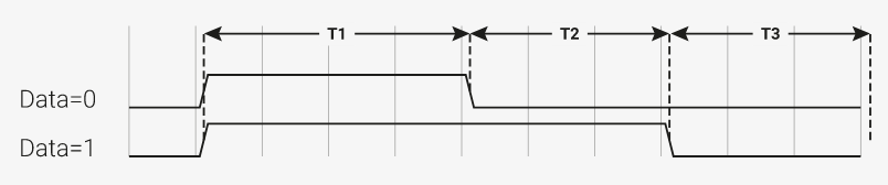
We’re talking about LEDs. The D stands for diode, which means that they only conduct electricity (and hence light up) in one direction. If you look at a factory fresh LED, one lead will be a bit longer than the other. This is the positive (+) or anode lead. The other is the negative (-) or cathode lead. The anode needs to be connected to a more positive voltage than the cathode, by about 3 volts, in order to light up. (How do you remember which one is the longer lead? Easy. A + sign, if taken apart and put back together end-to-end would be a bit longer than just a – sign. So the longer lead is the + lead.)

Imagine a grid of LEDs, say 4×4. You could address any individual LED with only 8 wires, 4 rows and 4 columns. (Schemes with even fewer wires are possible, but this is as dead simple as it gets.) For example, each row could have all 4 cathode leads connected, and each column all 4 anodes. It’s a little more complicated in three dimensions, effectively a 8×64 grid, but the basic principle is the same.
Assembling the grid
We’re definitely going to need a jig to hold each layer in place while we solder the LEDs. The instructions recommend using cardboard or possibly punchboard for this. There might even be some exactly fitting the needed dimensions, which for my kit were an exact 1cm spacing with 3mm holes for the LED. Imagining the horror that would ensue if I tried to hand-drill 64 accurate holes, I ended up 3D printing a jig, based on this design from Thingiverse. Since I don’t have a 3D printer, I used 3Dhubs to find someone nearby print it for me. It worked great, and it’s very precise.
With your jig ready, the next (and possibly most important) part is at hand: the bend. You need to bend evach LED’s leads in just the right way, so that once situated in the jig, the leads will be overlapping their neighbors. Take this part slow and get it exactly right.
Bending. So much bending.
The bend is one of the most critical parts of a quality assembly. You’re going to do this 512 times, so take your time and get things exactly right. In short, you need to do this:

Click to zoom. In all three cases, the longer anode lead is on the right.
In the middle LED, the anode lead is bent at a crisp 90 degree angle, pointing right into the camera. The bend is close to the LED body, only the width of the needle node pliers seen at the bottom. (I don’t like to make the bend flush against the plastic case, because that makes it too easy to damage the LED.)
On the right, the cathode is bent 90 degrees pointing left, but the bend is farther up the wire. There’s a little crimp mark on the lead that I use as a guideline. If you looked at it from a top down view, it would make a perfect L shape. Since the bends are at different distances from the LED body, this will allow the anode and cathode grids to cross over without touching. (Which would short out the display.)
Make sure all the bends are crisp and exactly right angles, including from the top-down view. This will make the next step easier.
Soldering. So much soldering.
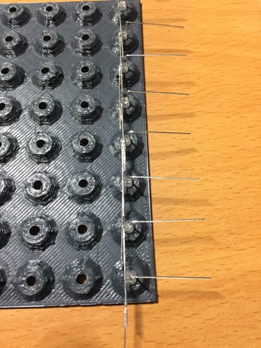
Starting from the bottom-right of your jig, place the first LED so that the leads are sticking out post both sides of the corner. Continue placing LEDs up the entire column. The anode wires should loosely overlap. If you haven’t already checked your LEDs, right now would be an excellent time to do so. (In my kit, if found one dead LED, and one shorted one, which would have caused havoc for the whole display.)
Here’s the trick to soldering quickly. In normal situations, making a good solder joint would involve heating the entire connector, while feeding in a bit of fresh rosin core solder. This is how it’s normally done, but in this case, you’re probably going to need one extra hand free to hold the wires in place. And we need to work extra quickly to not fry our LEDs.
So solder this way: with the wires snug up against each other for the entire length of their overlap (tweezer-assisted as needed) use a toothpick to apply a very small amount of flux to the junction between the two wires. We’re talking less than the volume of a sesame seed here.
Look at the image above. The layer of flux is there, but so thin you might’ve missed it without looking closely.
Wipe off the tip of your soldering iron so it’s clean and shiny. Melt a small blob of solder on the tip, and briefly press it to the fluxed, overlapping wires. The flux will make the solder wick between the wires, nearly instantaneously. PROTIP: you should be able to do this so quickly that even if you’re steadying the wire with your bare finger, a few centimeters away, you don’t get burned.
Remove heat and make sure everything stays absolutely still until the solder hardens. It should look like this, with the first column soldered, and the second column placed but not yet soldered:
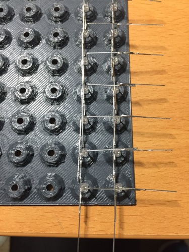
Continue on with the rest of the columns. Once you’ve finished all eight, congratulations. You’ve finished the first layer. Now do seven more layers.
Final assembly
Recall that electrically, the 8x8x8 grid is really more like a 64×8 array. On the board you’ll see the 8×8 grid, plus 8 more connectors close by. These extra eight are the return wires. We’ll call that side of the cube the front.
Carefully position one of your layers with anodes facing downward, and cathodes facing the front. Use your needle-nose pliers to slide all eight wires all the way into the connector. This will be frustrating. You’ll get all the way to the end and find one wire that didn’t go in. When you try to back things out a bit, several more wires will pop out, etc. Keep working on it until you have one layer fully connected on the bottom. Now–and this is important–test to make sure everything’s connected properly.
If you apply power without the return wires, nothing should light up. (After all, all those LEDs are so far only connected on one end.) If something does light up, that means you have a defective LED in that layer, and it’s leaking current in the reverse direction. If this happens to you, pull that layer off and replace the bad LED–generally the one that didn’t light up.
Connect a wire from one of the return terminals into any one of the front connectors, and power up your unit. Depending on the exact sequences it’s running through, at some point you should see some LED action.

Photo: It’s alive! Click to zoom.
Be on the lookout for any LEDs that don’t seem to ever light up, and replace them as needed.
Bit in all 8 layers this ways so that all 64 wires on the bottom are fully seated. Nearly there!
You’ll still have 64 wires sticking out the front. What do we do with these? Each horizontal row of 8 wires needs to be connected together. Maybe you could bend the LED leads to do this, but it would be hard to make it look good. I ended up using some tinned uninsulated bus wire. The conventional soldering method works here. Once you have 8 horizontal wires (each connecting to one side of 64 separate LEDs), hook up the return wires. Each layer goes to one of remaining 8 return wire sockets. It’s a good idea to do this in a temporary fashion, with jumper wires, to make sure everything’s fine. When it is, solder away.
Congratulations, you’ve finished your LED cube, and constructed a project more complicated than 99.99% of people in the world. Enjoy!