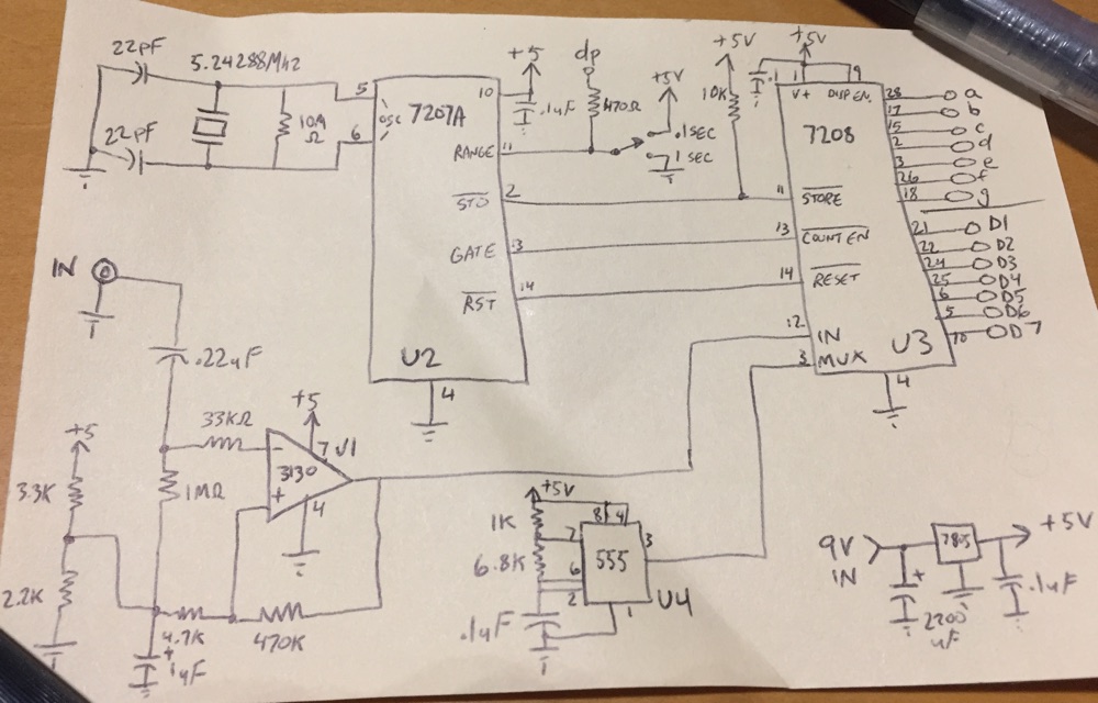
A blast from the past! While going through old stuff, I found this device, which I designed and assembled maybe 25 years ago. I never used it. I think it didn’t work on the first try, and I got distracted by other shiny things. Story of my life. I thoughtfully left my future self a schematic diagram.
Click to embiggen.
I don’t recall getting this out of a magazine. I came up with the design on my own, though I wouldn’t be surprised if either of these specialized ICs have a usage note with a similar circuit. It’s a pretty straightforward design. There’s a simple power supply, a JFET op amp input stage, a seven decade LED driver, a timebase, and a good old 555 timer driving the multiplexing.
The construction of the circuit is nothing to be proud of. (notice no pictures here!) It nicely fits on one of those pre-made circuit boards the same size and shape as a wireless breadboard.
Any electronics folks care to comment on this design? I’m more than tempted to fire it up and see if I can get it working. -m
Update: the more I look, more more odd the 555 section seems. There are two pin 3s marked on the 7208. I’m pretty sure that’s not how MUX is supposed to work. Time to pore over some old data sheets…
Update2: I removed the 555 circuit, and instead fed the existing MUX signal from pin 12 of the 7207a to pin 19 (MUX1) of the 7208. And wouldn’t you know, the thing works. I now have a fully functioning frequency counter.
It must be 25 years (or more!) since I’ve seen such a cct.
Certainly too long to comment on its viability etc Micah!
A bit of a nostalgia trip for me though. Thanks.
I’m tempted to ask readers if they know what a 555 is (without the aid
of Google)!